Latest Products


Contact Us
- The 3rd floor, Building A, Baolai Mansion, Hechang Road, Luozu Community, Shiyan Sub-district, Bao'an District, Shenzhen City
- sales@hualinkrf.com
- +86-755-88896526


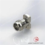
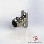
V Jack Edge Launch Connector
Description: 1.85 mm, Female, Straight, Edge Launch, PCB Connector (SUS), with .007" Pin (Solderless), Apply to Edge Launch PCB, Work to 67 GHz
● Insertion Loss Value: ≤ 0.49dB @ 67 GHz
● Durability Cycles: ≥ 500 Cycles
● Body Material: Stainless Steel
● Center Contact Material: Beryllium Copper
● 50 Ohms
Description
Introduction
This 1.85 mm connector (V wave band) uses a threaded interface, it possesses high precision structure with optimized impedance matching and stringent tolerance, that provide excellent electrical performance from DC to 67 GHz when connecting to PCB. Benefiting from Stainless steel design, it has outstanding durability in mechanically. The best advantage of this connector is "solderless" and "Reusable", which makes connectors can be easily applied to PCB and save a lot time and cost. It's called as 1.85 mm series due to inner diameter of body is 1.85 mm, it's very small internal size, very hard to machine and assembling, even small deviation will affect performance a lot.
Specification
Electrical | |
● Impedance: 67 Ω | ● Insulation Resistance: 5000 MΩ Min |
● Frequency Range: DC – 67 GHz | ● Dielectric Withstanding Voltage: 750 Vrms Min (Sea Level) |
● VSWR: 1.30 Max @ 67 GHz | ● Contact Resistance: ≤ 3 mΩ (Center Contact) |
● Insertion Loss: ≤ 0.49 dB @ 67 GHz | ≤ 2 mΩ (Outer Contact) |
Mechanical | |
● Mateable with 2.4 mm, V Series | ● Center Contact Retention Force: 6 lbs Min |
● Durability: ≥ 500 Cycles | ● Coupling Torque: 7- 8 lb-in Recommended |
Environmental | |
● Temperature Range: -55 ℃ to +85 ℃ | |
Material & Finish | |
● Body: SUS303, Passivated | ● Dielectric: Engineering Plastic, Natural |
● Center Contact: Beryllium Copper, 30 μ" Gold | |
Features and Benefits
● Gold Plated Beryllium Copper Contact
● Stainless Steel Design
● Reusable
● Solderless
Applications
● RF System
● EMC
● High Speed Cable Test
● Fiber optic transceiver testing
● Wireless
Outline Drawing

FAQ
1. The terminate type of RF PCB connector
The same series connector also has different terminations.
Hulink PN Code | Termination Type | Example |
TH | Through Hole PCB |
|
MT | Mixed Tech PCB |
|
EM/EF | Edge Mount PCB |
|
EQ | Edge Launch PCB |
|
EL | End Launch PCB |
|
TP | Surface Launch PCB |
|
TR | Panel\Accept Pin |  |
TC | Panel\Cylinder Probe |
|
TD | Panel\Dielectric-Extrude Probe |
|
TL | Panel\Ladder Probe |
|
HM | Horse Mount PCB |
|


2. How to choose the RF PCB connector?
Usually, we find a suitable connector by the below parameters:
■ Your characteristic impedance is 50 ohms or 75 ohms
■ The working frequency of your system?
■ The method of installation is solder or solderless?
■ The electrical performance requirements like VSWR and IL
Packaging, Shipping

Hot Tags: v jack edge launch connector, China, suppliers, customized, OEM, ODM, K Female 2 Hole Flange Panel Connector, 3.5 mm Armored Test Cables, 2.92 mm/ 2.4 mm Attenuators, 2.92 To 2.92 Ultra-flex Test Cables, K Jack Connector Vertical Launch, SMA Male To SMA Male Cable Assemblies
You Might Also Like