Latest Products


Contact Us
- The 3rd floor, Building A, Baolai Mansion, Hechang Road, Luozu Community, Shiyan Sub-district, Bao'an District, Shenzhen City
- sales@hualinkrf.com
- +86-755-88896526


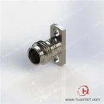
V Connector End Launch Low Profile 67 GHz
Description: 1.85 mm, Female, Straight, End Launch (standard and low profile), PCB Connector, with .005" Pin (Solderless), Apply to End Launch PCB , Work to 67 GHz
● VSWR: 1.30 Max @ 67 GHz
● Insertion Loss: ≤ 0.49 dB @ 67 GHz
● Mating/unmating Life: ≥ 500 Cycles
● SMA Body Material: Stainless Steel
● Housing Material: Brass
● Contact Pin Material: Becu
Description
Introduction
Hualink high-performance 1.85 mm female End Launch connectors are designed to provide less reflection up to 67 GHz for single-layer and multi-layer printed circuit boards where the high-frequency signal is on the top layer. It's designed into 2 pieces for more stable installation on PCB, solderless design for both grounding and signal make it high-efficiency to install or uninstall, which save a lot of time and cost. Comparing to Standard High Profile version, low profile is more suitable if application limit the space. This 1.85 mm connector is good to work in V wave band, and very sensitive to dimension/tolerance, usually used in precision test application.
Specification
Electrical | |
● Impedance: 50 Ω | ● Insulation Resistance: 5000 MΩ Min |
● Frequency Range: DC – 67 GHz | ● Dielectric Withstanding Voltage: 500 Vrms Min (Sea Level) |
● VSWR: 1.30 Max @ 67 GHz | ● Contact Resistance: ≤ 3 mΩ (Center Contact) |
● Insertion Loss: ≤ 0.49 dB @ 67 GHz | ≤ 2 mΩ (Outer Contact) |
Mechanical | |
● Mateable with 2.4 mm, V Series | ● Center Contact Retention Force: 6 lbs Min |
● Durability: ≥ 500 Cycles | ● Coupling Torque: 7- 8 lb-in Recommended |
Environmental | |
● Temperature Range: -55 ℃ to +85 ℃ | |
Material & Finish | |
● Body: Brass and SUS303 | ● Dielectric: Engineering Plastic and PTFE, Natural |
● Center Contact: Beryllium Copper, 30 μ" Gold | |
Features and Benefits
● Fixed by screws directly, convenient
● Good Return Loss
● Low Insertion Loss
● Low RF Leakage
● High Precision
● Excellent Repeatability
Applications
● Optical Module Test
● 5G Test
● High Speed Data RF Test
● RF System Engineering
● Communications
● Aerospace
Outline Drawing

Related Products
Hualink PN | DESCRIPTION | Picture |
185-S-P-HPN-ST-EL0090-01 | 1.85 mm Female Straight End Launch (Solderless) |
|
185-S-P-HPN-ST-EL0090-01L | 1.85 mm Female Straight End Launch (Solderless) |
|
185-S-P-HPN-ST-EL0120-01 | 1.85 mm Female Straight End Launch (Solderless) |
|


FAQ
1. End Launch Connectors – Installation Procedure
Step 1: Mount the end launch connector on the board in the desired position through 2 holes.
Step 2: Ensure the launch pin is centered on the signal trace of PCB.
Step 3: Ensure the housing is tight against the side face of PCB.
Step 4: Tighten the 1-72 mounting screws until the connector is not moving.
Step 5: Keep PCB and Connectors clear
2. Cut-off frequency of RF connector?

Packaging, Shipping

Hot Tags: v connector end launch low profile 67 ghz, China, suppliers, customized, OEM, ODM, K Series RF Cable Assembly, 1.85 mm To 1.85 mm Adapter, SMA Jack Through Hole RF Connector, V Jack Edge Launch Connector, 3.5 mm Female Edge Mount Connector 34 GHz, SMA To SMA Durable Test Cables
You Might Also Like