Latest Products


Contact Us
- The 3rd floor, Building A, Baolai Mansion, Hechang Road, Luozu Community, Shiyan Sub-district, Bao'an District, Shenzhen City
- sales@hualinkrf.com
- +86-755-88896526


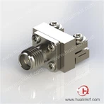
SMA Female Flange Mount Connector 4-Hole
Description: SMA, Female, Straight, Receptacle, Panel Connector (SUS), Accept .020" Pin, Apply to Panel, Work to 26.5 GHz
● VSWR: 1.30 Max @ 26.5 GHz
● Insertion Loss: ≤ 0.31 dB @ 26.5 GHz
● Durability: ≥ 500 Cycles
● Body Material: SUS 303
● Center Contact Material: Becu
Description
Introduction
Hualink SMA 4 holes flange RF connector includes a Teflon dielectric, a passivated stainless steel body, and a heavy gold plated beryllium copper. This SMA female 4 holes flange connector is developed for application up to 26.5 GHz and accepting .020 inch pin, it's easy to connect and disconnect on panel, which help customers to upgrade system easily. It's widely used in splitters, combiners, circulators etc. Comparing 2 holes design, 4 holes version provide firmer fixing but will take up more space.
Specification
Electrical | |
● Impedance: 50 Ω | ● Insulation Resistance: 5000 MΩ Min |
● Frequency Range: DC – 26.5 GHz | ● Dielectric Withstanding Voltage: 500 Vrms Min (Sea Level) |
● VSWR: 1.30 Max @ 26.5 GHz | ● Contact Resistance: ≤ 3 mΩ (Center Contact) |
● Insertion Loss: ≤ 0.31 dB @ 26.5 GHz | ≤ 2 mΩ (Outer Contact) |
Mechanical | |
● Mateable with 3.5 mm, 2.92 mm, SMK, K Series | ● Center Contact Retention Force: 6 lbs Min |
● Durability: ≥ 500 Cycles | ● Coupling Torque: 7-10 lb-in Recommended |
Environmental | |
● Temperature Range: -65 ℃ to +165 ℃ | |
Material & Finish | |
● Body: Stainless Steel, Passivated | ● Dielectric: Teflon |
● Center Contact: Becu, 30 μ" Gold | |
Features and Benefits
● Gold Plated heat treated Becu Contact
● 4 Holes Flange Design
● DC - 26.5 GHz
● Reusable
Applications
● Instrumentation
● Satellite Communication Equipment (SATCOM)
● Splitters, combiners, circulators etc.
● General Purpose Test
Product details

Outline Drawing

Related Product
Hualink PN | DESCRIPTION | Picture |
SMA-S-PF-HPP-ST-TR0090-W2 | SMA Female Straight Receptacle |
|
SMA-P-PF-HPP-ST-TR0090-W3 | SMA Male Straight Receptacle |
|
SMA-P-PF-HPP-ST-TR0120-W3 | SMA Male Straight Receptacle |
|
SMA-S-PF-MPP-ST-TR0120-02 | SMA Female Straight Receptacle |
|
SMA-S-PF-HPP-ST-TR0120-03 | SMA Female Straight Receptacle |
|
SMA-P-PF-HPP-ST-TR0150-W2 | SMA Male Straight Receptacle |
|
SMA-S-PF-HPP-ST-TR0150-W3 | SMA Female Straight Receptacle |
|
SMA-P-PF-HPP-ST-TR0180-W2 | SMA Male Straight Receptacle |
|
SMA-S-PF-HPP-ST-TR0180-W3 | SMA Female Straight Receptacle |
|
SMA-P-PF-HPP-ST-TR020-W2 | SMA Male Straight Receptacle |
|
SMA-S-PF-HPP-ST-TR0200-W2 | SMA Female Straight Receptacle |
|


FAQ
1. A measure of how much power is reflected
■ Return Loss: The portion of a signal that is lost due to a reflection of power at a line discontinuity. Return Loss is similar to VSWR and is generally preferred in the CATV industry to a VSWR specification
Return Loss = Ratio of reflected to incident power in dB
■ VSWR: Acronym for Voltage Standing Wave Ratio. VSWR is the ratio of voltage applied to voltage reflected. It is the major factor contributing to the total signal efficiency of the connector.
VSWR = Ratio of maximum to minimum electric field (Voltage)
■ Best performance is achieved when the impedance of the cable and the connector are the same (matched)
2. Insertion Loss
■ Insertion Loss is expressed in dB, and is a measure of the total loss of power going through a device
IL = -20*log (Pout/Pin)
■ Includes losses due to reflection (usually the dominant factor unless the Return Loss is very low <-26 dB), plus losses due to the dielectric and metal conductors (Attenuation)
3. Passive Intermodulation Distortion
■ Spurious Signals created by non-linear mixing of 2 or more frequencies in a passive device
FIM3 = 2* F1-F2
■ dBm: measure of power relative to 1 milliwatt
■ dBc: measure of dB below a specified carrier level
Packaging, Shipping

Hot Tags: sma female flange mount connector 4-hole, China, suppliers, customized, OEM, ODM, 3.5 mm Connectors, V Jack Connector Vertical Launch 67 GHz, SMA Female Flange Mount Connector 4-Hole, 2.4 mm To 2.4 mm Adapter, High Speed Test Flexible Cable Assembly, 1 mm W1 Connectors
You Might Also Like