Latest Products


Contact Us
- The 3rd floor, Building A, Baolai Mansion, Hechang Road, Luozu Community, Shiyan Sub-district, Bao'an District, Shenzhen City
- sales@hualinkrf.com
- +86-755-88896526

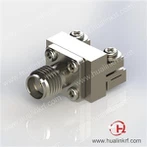
SMA Female End Launch Connector RF
Description: SMA, Jack, Straight, End Launch (High Profile), PCB Connector (Brass and Stainless Steel), with .007" Pin (Reusable), Apply to End Launch PCB , Work to 26.5 GHz
● VSWR: 1.30 Max @ 26.5 GHz
● Insertion Loss: ≤ 0.31 dB @ 26.5 GHz
● Durability: ≥ 500 Cycles
● SMA Body Material: SUS303
● Housing Material: Brass
● Center Contact Material: Beryllium Copper
Description
Introduction
Hualink high-precision SMA End Launch connectors are designed to provide low VSWR up to 26.5 GHz for single-layer and multi-layer edge mount PCB where the signal trace is on the top layer. It's designed into 2 sections for more stable installation on PCB, solderless design of both outer contact and signal contact make it high-efficiency to connect or disconnect, which make sharing test PCB possible and save much cost.
Specification
Electrical | |
● Impedance: 50 Ω | ● Insulation Resistance: 1200 MΩ Min |
● Frequency Range: DC – 26.5 GHz | ● Dielectric Withstanding Voltage: 500 Vrms Min (Sea Level) |
● VSWR: 1.30 Max @ 26.5 GHz | ● Contact Resistance: ≤ 3 mΩ (Center Contact) |
● Insertion Loss: ≤ 0.73 dB @ 26.5 GHz | ≤ 2 mΩ (Outer Contact) |
Mechanical | |
● Mateable with 3.5 mm, 2.92 mm, SMK, K Series | ● Center Contact Retention Force: 6 lbs Min |
● Durability: ≥ 500 Cycles | ● Coupling Torque: 7-10 lb-in Recommended |
Environmental | |
● Temperature Range: -55 ℃ to +165 ℃ | |
Material & Finish | |
● Body: Brass and Stainless Steel | ● Dielectric: Engineering Plastic, Natural |
● Center Contact: Beryllium Copper, Heavy Gold | |
Features and Benefits
● Low VSWR, Easy to Match with PCB
● Low Insertion Loss
● Low RF Leakage
● Rugged & Durable
● High Quality
Applications
● Optical Module Test
● Instrumentation
● Test Equipment
● Telecommunications
● Aerospace
● Military
Outline Drawing

FAQ
1. End Launch Connectors – Installation Procedure
Step 1: Mount the end launch connector on the board in the desired position.
Step 2: Ensure the launch pin is centered on the trace.
Step 3: Ensure the transition block is tight against the board.
Step 4: Tighten the 1-72 mounting screws until the connector is secure.
2. Definitions
Coplanar ground plane spacing = trace width + gap + gap. This is the distance from the inside edge of one top ground plane to the inside edge of the other top ground plane.
Microstrip-to-coplanar transition = When using microstrip on a multilayer board or on a board where the microwave ground is not accessible, then a microstrip-to-coplanar transition should be used.
Transition Block = The portion of the End Launch connector assembly where the high frequency signal transition from the coax connector onto the printed circuit board.
Ground stitching = These are vias connecting the top ground planes with the substrate ground. The purpose of the vias is to ensure both coplanar ground planes stay at the same potential. The best placement of these is near the trace at a distance of ¼ wavelength of the highest frequency.
Packaging, Shipping

Hot Tags: sma female end launch connector rf, China, suppliers, customized, OEM, ODM, Low Loss Flexible Coax Cables 18 GHz, 2.4 mm Armored Test Cables, SMA To N Type Low Loss Test Cables, SMA Fixed Attenuators, 3.5 mm Armored Test Cables, Type N RF Terminations
You Might Also Like