Latest Products


Contact Us
- The 3rd floor, Building A, Baolai Mansion, Hechang Road, Luozu Community, Shiyan Sub-district, Bao'an District, Shenzhen City
- sales@hualinkrf.com
- +86-755-88896526
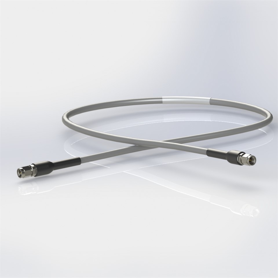
SMA RF Low Loss Test Cables
Description: SMA Male to SMA Male, Ultra-Low Loss, Phase stable Test Cable Assembly, DC to 18 GHz
● Impedance: 50 ohms
● VSWR: 1.30 Max @ 18 GHz
● Insertion Loss: 0.68 dB per Meter at 18GHz
● Durability: ≥ 500 Cycles
● Connector Body Material: Stainless Steel
● Center Contact Material: Brass, Gold Plated
Description
Introduction
Hualink SFB series super low loss phase stable test cables provide higher performance than typical low loss and phase stable cables. It offers extra low loss, light weight, and high phase stability versus mechanical and temperature changes. This cable series features a silver-plated copper center conductor, low density PTFE dielectric, silver-plated copper tape wrapping outer conductor, and a silver-plated copper braid shield, and grey FEP outer jacket. The Outer diameter/OD of cable is 7.8mm, big size and high Vp provide very low insertion loss, that's why it allows overall length to 4 meters, 8 meters even more.
Specification
Electrical | |
● Impedance: 50 Ω | ● Insulation Resistance: 1000 MΩ Min |
● Frequency Range: DC – 18 GHz | ● Dielectric Withstanding Voltage: 1500 Vrms Min (Sea Level) |
● VSWR: 1.30 Max @ 18 GHz | ● Velocity of Propagation: 83% |
● Insertion Loss: ≤ 0.67 dB per meter@ 18 GHz | ● Shielding Effectiveness: 90dB |
Mechanical | |
● Durability: ≥ 500 Cycles | ● Recommended mating torque: 7-10 lb-in (SMA) |
● Preferred bending radius: 80mm | ● Connector retention force: >200N |
Environmental | |
● Temperature Range: -55 ℃ to +85 ℃ | |
Material & Finish | |
● Cable Jacket: Gray FEP | ● Stainless Steel passivated connectors |
● Cable features: Super low loss and flexible | |
Features and Benefits
● Broad Frequency Response
● Ruggedness & Durability
● Low Attenuation
● RF stability with flexure
● high velocity of propagation (83% speed of light)
Applications
● Extra low temperature-related phase change
● RF Module Testing
● Scalar Analyzers
● Radio stations
● Feeder cable
Test Date

DUT: SMA male to SMA male super low loss cable assembly. Length = 8meters
FAQ
1. What are the Advantages of the 4.3/10 Connector Interface?
DIN 7/16, N-type, 4.3/10, and 4.1/9.5 are all coaxial cable standard types used in wireless infrastructure and mobile wireless equipment. Each are different in size, power handling, frequency, and other electrical and mechanical specifications. Specifically, 4.3/10 and 4.1/9.5 are more compact versions of DIN 7/16, optimally designed for use in dense interconnect scenarios, such as distributed-antenna systems (DAS) for connections between the base station and remote radio units (RRUs). Both 4.3/10 and 4.1/9.5 are more compact and present much better torque specifications and passive intermodulation (PIM) distortion metrics compared to N-type connectors, which make them better suited for reliable installation for wireless infrastructure and to account for the increased PIM requirements of the modern crowded spectrum and congested tower sites.
4.1/9.5 precedes 4.3/10, and the connector standards are, in many ways, similar. However, 4.3/10 connector standards are designed to more completely address modern application requirements by its low PIM under various torque conditions allowing enhanced reliability and hand-tightening, and 4.3/10 has separate mechanical and electrical planes, providing enhanced PIM performance. Hence, 4.3/10 is continually likely to increase in adoption over 4.1/9.5
2. Solderless Vertical Launch Connectors advantage & disadvantage
Since 5G will be in commercial use next year, more and more products require higher performance. Products are more precise, tiny, and convenient. That's why we designed these solderless PCB connectors.
Now, we have designed/manufactured the full series of these vertical launch connectors (DC to 67 GHz). And there are two versions for selection, standard (the left one of below picture) and tunnel(the right one of below picture) type. The difference between them is the mated PCB has less/more space for Layout/prototype. It depends on your application. While their performance does not have much difference.
About their advantage as following:
1) Due to those are precision connectors, mated PCBs also are high performance. In other words, if the connectors do not be soldered well, those expensive PCBs will be damaged. But if you choose solderless ones, you can install or remove them easily and will not affect PCBs. They are fixed with screws (accessories are free to supply). Therefore it is more affordable,convenient and reusable.
2) Those connectors are in small size. And as its vertical launch placement, they can be assembled on the PCB with a small pitch. It is about 15mm. It can help you to make your products smarter. Like below pictures.
3) The material is passivated stainless steel outer conductors and gold-plated beryllium copper center contacts.
The disadvantage is they are less stable than soldered items. As those connectors are installed with screws, they usually used in the testing application. But if you want the high performance soldered connectors.
Packaging, Shipping

Hot Tags: sma rf low loss test cables, China, suppliers, customized, OEM, ODM, 3.5 mm Female Edge Mount Connector 34 GHz, SMA Female Flange Mount Connector 4-Hole, 3.5 mm Jack Edge Mount Connector 4 Legs, Cable Assembly, SMA To SMA Adapters, K Series RF Cable Assembly
You Might Also Like